- TRUNNION BALL VALVE
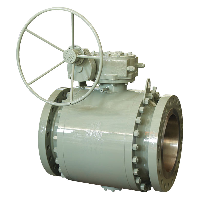
- CAST TRUNNION BALL VALVE (Splited body, side-entry)
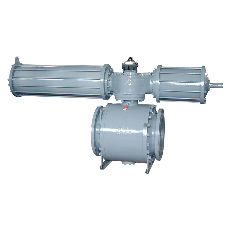
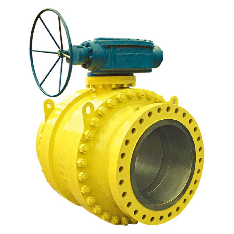
- FORGED TRUNNION BALL VALVE (Splited body, Fixed-shaft structure)
- FORGED TRUNNION BALL VALVE (Splited body, Support plate structure)
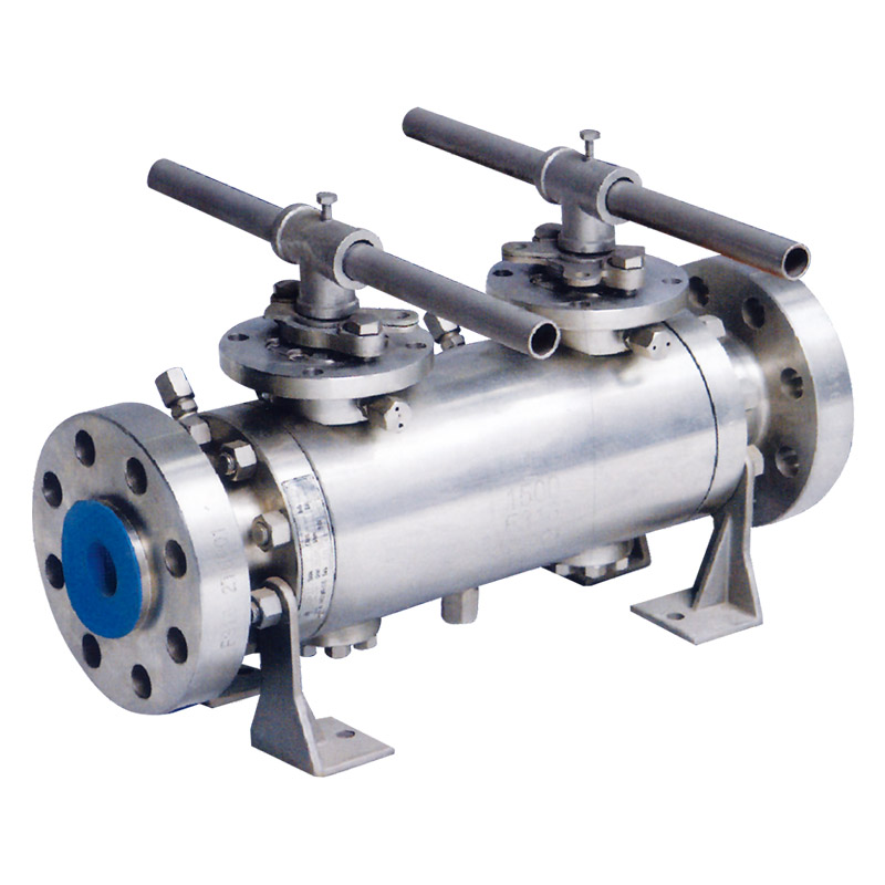
- DOUBLE BLOCK AND BLEED VALVE
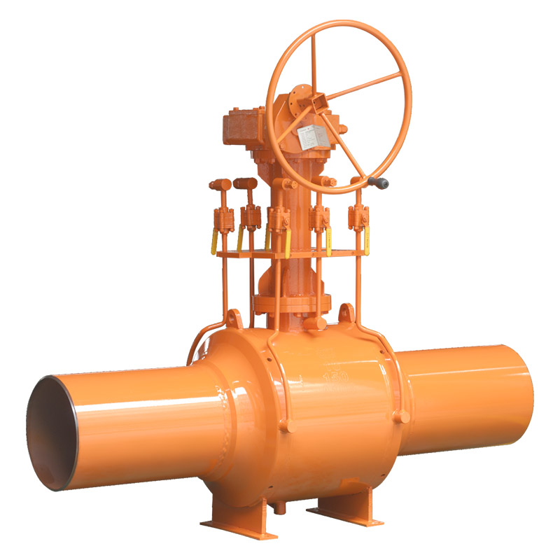
- FULL WELDED BALL VALVE
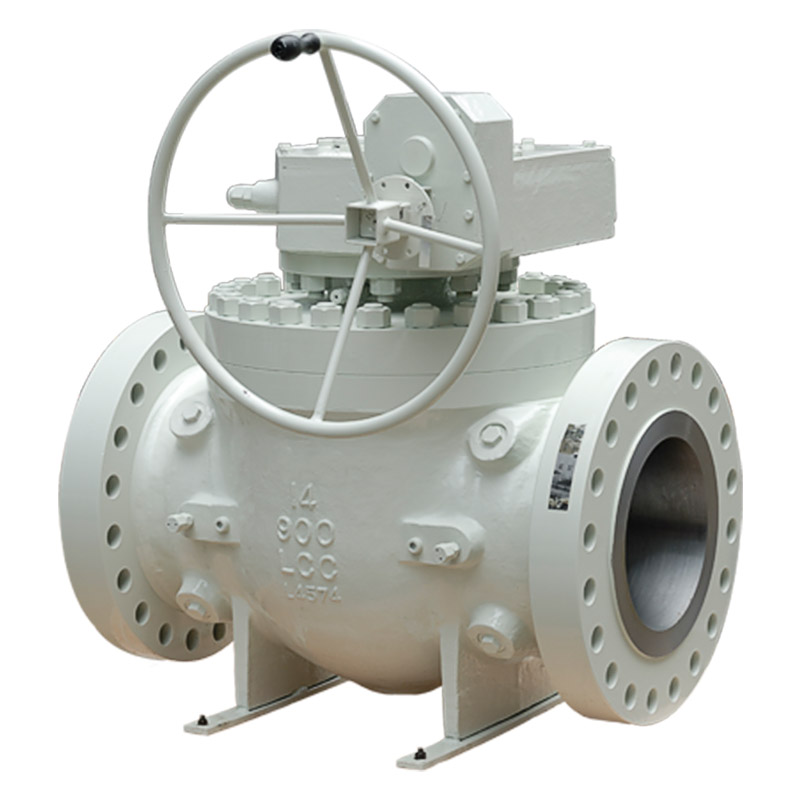
- TOP ENTRY BALL AVLVE
- CONFIGURATION OF BALL VALVE DRIVING DEVICE
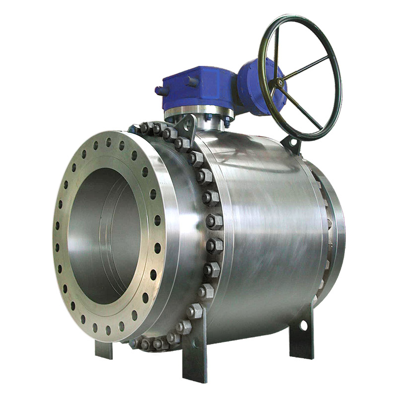
FORGED TRUNNION BALL VALVE (Splited body, Support plate structure)
-
Share:
Nominal diameter(in): NPS 2ˇ48
Nominal pressure(Class): Class150ˇClass900
Design and manufacturing: API 608ˇAPI 6D
Face-to-face dimensions: ASME B16.10ˇAPI 6D
Pressure test: API 598ˇAPI 6D
Transmission mode: Manual, worm and worm gear transmission, pneumatic, electric
Description
USAGE
The trunnion ball valve is used to cut off or connect the media in various pipelines of Class150ˇClass2500. The valves made of different materials are suitable for various media such as water, steam, oil, liquefied gas, natural gas,coal gas, nitric acid, oxidizer, urea and etc. The driving modes include manual operation, worm and worm gear transmission, pneumatic operation and electric operation. The connection ends can be flange or butt welding.
DESIGN STRUCTURAL FEATURES
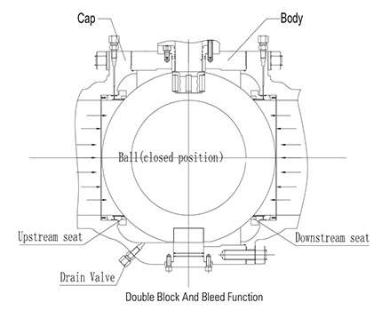
1. Double Block And Bleed(DBB)
When the valve is closed and the middle cavity is emptied through the discharge
valve, the upstream and downstream seats will independently block the fluid at the
inlet and outlet to realize double block function. Another function of the discharge
device is that the valve seat can be checked if there is any leakage during the test.
In addition, the deposits inside the body can be washed and discharged through the
discharge device to reduce damage to the seat by impurities in the medium.When the valve is closed and the middle cavity is emptied through the discharge valve, the upstream and downstream seats will independently block the fluid at the inlet and outlet to realize double block function. Another function of the discharge device is that the valve seat can be checked if there is any leakage during the test. In addition, the deposits inside the body can be washed and discharged through the discharge device to reduce damage to the seat by impurities in the medium.
2. Low Operating Torque
The trunnion pipeline ball valve adopts trunnion ball structure and floating valve seat, so as to achieve lower torque under operating pressure. It uses self-lubricating PTFE and metal sliding bearing to reduce the friction coefficient to the lowest in conjunction with the high intensity and high fineness stem.
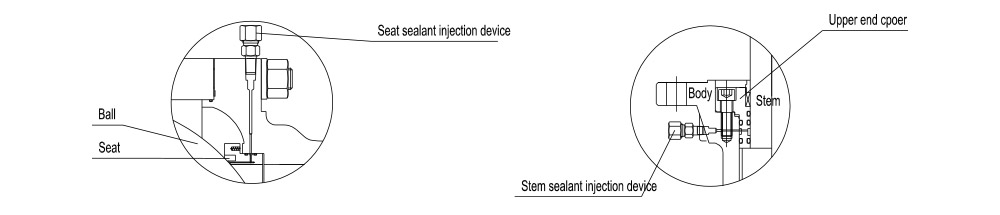
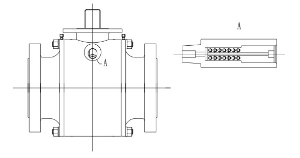
3. Emergency Sealing Device
The ball valves with the diameter more than or equal to 6''(DN150) are all designed with sealant injection device on stem and seat.When the seat ring or stem O ring is damaged due to accident, the corresponding sealant can be injected by the sealant injection device to avoid medium leakage on seat ring and stem.If necessary, the auxiliary sealing system can be used for washing and lubricating the seat to maintain its cleanliness.
sealant Injection Device
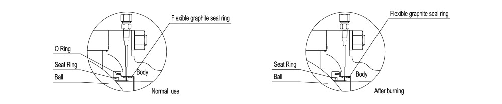
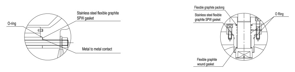
4. Fire-safe design structure
Fire during the use of valve, the seat ring, stem O ring and middle flange O ring made of PIFE, rubber or other non-metal materials will be decomposed or damaged under high temperature. Under pressure of the medium, the ball valve will push the seat reatainer rapidly towards the ball to make the metal seal ring contact the ball and form the auxiliary metal to metal sealing structure, which can effectively control valve leakage. The fireproof structure design of trunnnion pipeline ball valve conforms to requirements in API 607, API 6FA, BS6755 and other standards.
Fire-safe design structure of seat
Fire-safe design structure of middle flange
5. Anti-static design structucture
The ball valve is provided with the anti-static structure and adopts ths static electricity discharge device to directly form a static channel between the ball and body or form a static channel between the ball and body through the stem, so as to discharge the static electricity produced due to friction during theopening and closing of ball and seat through the pipeline, avoiding fire or explosion that may be caused by static spark and ensuring system safety.
6. Reliable seat sealing design structure
The seat sealing is realized through two floating seat retainers. They can float axially to block the fluid, including ball sealing and body sealing. The low pressure sealing of valve seat is realized by spring pre-tightening. In addition, the piston effect of valve seat is designed reasonably, which realizes high pressure sealing by the pressure of the medium itself. The following two kinds of ball sealing can be realized.
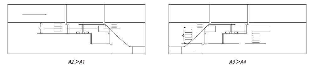
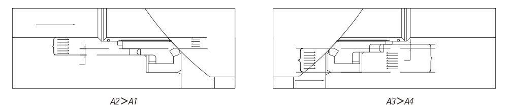
7. Single Sealing(automatic Pressure Relief In Middle Cavity Of Vavle)
Generally, the single sealing structure is used, that is, there is only the upstream sealing. As the independent spring loaded upstream and downstream sealing seats are used, the over-pressure inside valve cavity can overcome the pre-tightening effect of the spring, so as to make the seat release from the ball and realize automatic pressure relief towards the downstream part.
The upstream side: When the seat moves axially along the valve, the pressure P exerted on the upstream part(inlet) produces a reverse force on A1. As A2 is higher than A1, A2-A1=B1,The force on B1 will push the seat to the ball and realize tight sealing of the upstream part.
The downstream side: Once the pressure pb inside the valve cavity increases, the force exerted on A3 is higher than that on A4. As A3-A4=B2, The pressure differential on B2 will overcome the spring force to make the seat release from the ball and realize pressure realif of valve cavity to the downstream part. Afterwards, the seat and ball will be sealed again under the spring action.
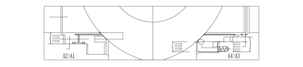
8. Double Sealing (double Piston affect)
The trunnion pipeline ball valve can be designed with the double sealing structure before and after the ball for some special service conditions and user requirements. It has double piston effect. Under normal condition, the valve generally adopts primary sealing. When the primary seat sealing is damaged and causes leakage, the secondary seat can play the function of sealing and enhance the sealing reliability. The seat adopts the combined structure.The primary seal is metal to metal seal.The secondary seal is fluorine rubber O ring that can ensure the ball valve can reach the bubble level sealing.When the pressure differential is very low, the sealing seat will press the ball through the spring action to realize primary sealing. When the pressure differential rises,the sealing force of seat and body will increase accordingly so as to tightly seal the seat and ball and ensure good sealing performance.
Primary sealing: Upstream. When the pressure differential is lower or there is no pressure differential, the floating seat will move axially along the valve under the spring action and push the seat towards the ball to keep tight sealing. When the pipeline pressure P increases, the force exerted on the area A2 of valve seat is higher than the force exerted on the area A1, A2-A1=B1. Therefore, the force on B1 will push the seat towards the ball and realize tight sealing of the upstream part.
 9. Safety Relief Device
As the ball valve is designed with the advanced primary and secondary sealing that has double piston effect, and the middle cavity cannot realize automatic pressure relief, the safety relief valve must be installed on the body in order to prevent the danger of over-pressure damage inside the valve cavity that may occur due to thermal expansion of medium. The connection of the safety relief valve is generally NPT1/2.
Another point to be noted is that the medium of the safety rel- ief valve is directly discharged into the atmosphere. In case direct discharging into the atmosphere is not allowed, we suggest that the ball valve with a special structure of automatic pressure relief towards upper stream should be used. Refer to the following for details. Please indicate it in the order if you do not need the safety relief valve or if you would like to use the ball valve with the special structure of automatic pressure relief towards upper stream.
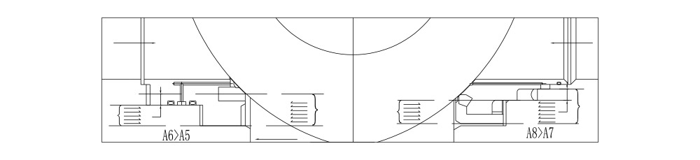
10. Secial Structure Of Automatic Pressure Relief Towards Upper Stream
As the ball valve is designed with the advanced primary and secondary sealing that has double piston effect, and the middle cavity cannot realize automatic pressure relief, the ball valve with the special structure is recommended to meet the requirement of automatic pressure relief and ensure no pollution to the environment. In the structure, the upper stream adopts primary sealing and the lower stream adopts primary and secondary sealing. When the ball valve is closed,the pressure in the valve cavity can realize automatic pressure relief to the upper stream, so as to avoid the danger caused by cavity pressure. When the primary seat is damaged and leaks, the secondary seat can also play the function of sealing. But special attention shall be paid to the flow direction of the ball valve. During the installation, note the upstream and downstream directions. Refer to the following drawings for sealing principle of the valve with the special structure.
Principle drawing of ball valve upstream and downstream sealing
Principle drawing of ball valve cavity pressure relief to the upper steam and of downstream sealing
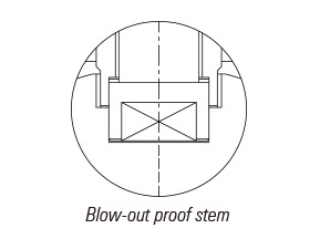 11. Blow-out Proof Stem
The stem adopts the blow-out proof strucrure. The stem is designed with the footstep at its bottom so that with the positioning of upper cover and screw, the stem will not be blown out by the medium even in case of abnormal pressure rise in the valve cavity.
 12. Corrosion Resistance and Sulfide Stress Resistance
Certain corrosion allowance is left for the body wall thickness. The carbon steel stem, fixed shaft, ball, seat and seat ring are subjected to chemical nickel plating according to ASTM B733 and B656. In addition, various corrosion resistant materials are available for users to select.
According to customer repuirements, the valve materials can be selected according to NACE MR 01 75/ISO 15156 or NACE MR 0103, and strict quality control and quality inspection should be carried out during the manufacturing so as to fully meet the requirements in the standards and meet the service conditions in sulfurization environment.
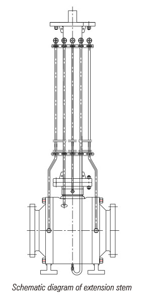
13. Extented Stem design for underground application
As for the embedded valves, the extension stem can be supplied if ground operation is needed. The extension stem is composed of stem, sealant injection valve, and drainage valve that can be extended to the top for the convenience of operation.
Users should indicate the extension stem requirements and length when placing orders. For ball valves driven through electric, pneumatic and pneumatic-hydraulic operations, the extension stem length should be from the centre of pipeline to top flange.
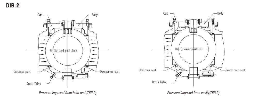
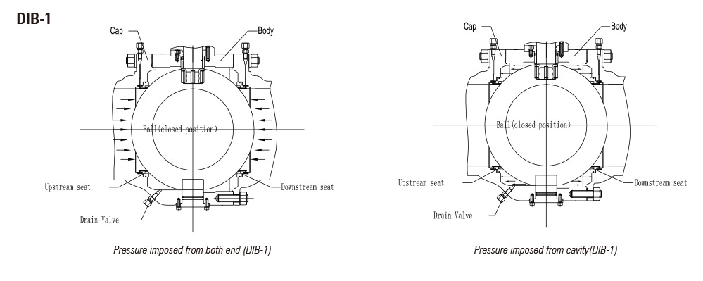
14. Double isolation and bleed valve (DIB design)
There are two type of DIG design ball valves, one type is double bi-directional seats(DIB-1), and the other type is single bi-direction seat plus unidirectional seat (it have direction mark on the valves, DIB-2), With two sealing surfaces, each sealing faces resist to a source of pressure in the closed position, through bleeder valve chamber between the sealing faces. For DIB-1: Both seats are Bi-directional sealing, Each seat should be tested Bi-directionally;
For DIB-2: One is unidirectional sealing seat, and the other is Bi-directional sealing seat, so there is a direction marked on the body for this type of ball valve; The Bi-directional sealing seat need be tested Bi-directionally. As to the unidirectional sealing seat. It should be tested unidirectionally (Add pressure to valve chamber and upstream, examine leakage status of downstream valve seat)
Send Inquiry
Please feel free to contact with us at sales@leadervalve.com.cn or filling up an enquiry form instructed at the bottom, You will get an effective response within 24 hours from Our sales representative. Thanks for your valued time with interest!